Transmission Line Calculator March 6, 2007
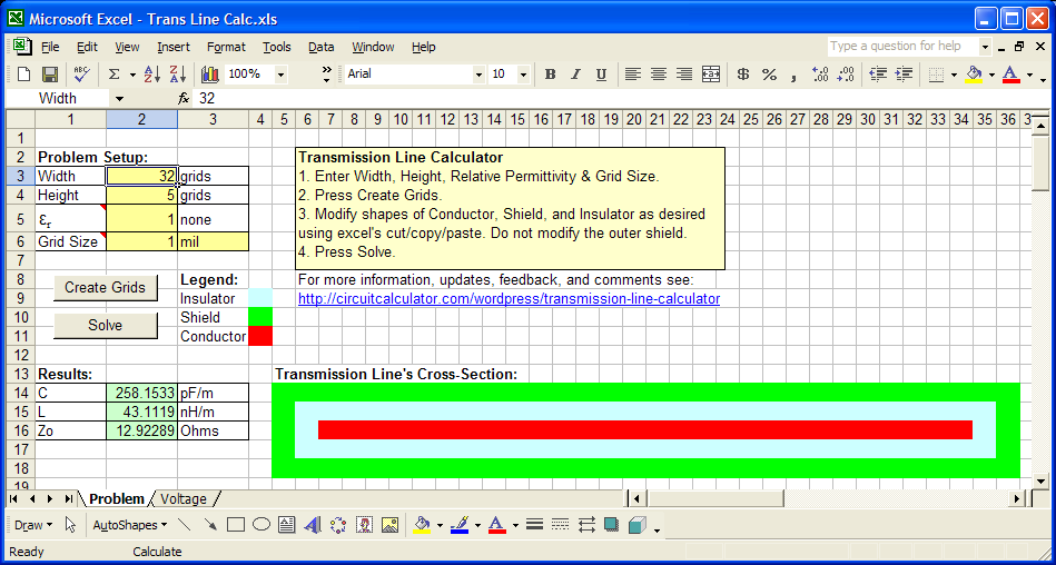
The Excel based tool (see link below) calculates the capacitance and inductance per unit length as well as the impedance of a transmission line. It may be applied to wires, PCBs, etc.
A cross section of the transmission line is drawn into the Excel grids using different colors to represent the conductor, shield (return), and insulator. A finite element model of the transmission line is then solved with 1 Volt applied to the conductor with respect to the shield. The voltages throughout the insulator are found. This allows the stored energy, capacitance, inductance and impedance to be found.
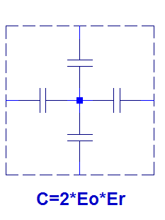
Each grid of the insulator can be thought of as 4 capacitors each having a capacitance per unit length of 2*Eo*Er where Eo is 8.854 pF/m and Er is the relative permittivity of the material (see figure below). Once the total capacitance is found, the inductance per unit length is then:
L = Mu*Eo*Er/C (in nH/m)
where Mu = 1257 nH/m
And the impedance is then:
Z = SQRT(L/C)
Instructions:
1. RIGHT-CLICK, download, and save this file on your computer:
http://circuitcalculator.com/wordpress/wp-content/uploads/2007/03/trans-line-calc.xls
(Left-Clicking and/or Opening in browser DOES NOT WORK.)
2. Close any open instances of Excel that are running on your computer.
3. After saving, open the file. It contains macros, so you may see a warning. Macros must be enabled for it to work.
- Posted in : Calculators, Electrical Engineering, Excel, PCB
- Author : Brad
Comments
Can you post copy of excel file?
Kumar,
There was a link inside the post, but it was hard to see. I have moved it to the bottom of the article and added instructions.
Thanks,
Brad
Brad,
I really like the transmission line Excel program. Is there a book that you used that details how the calculations are done?
Best regards,
Richard
Richard,
I don’t have a specific book I am using. I can’t remember exactly where I leaned how to solve field equations with Excel, but have been doing it for a while. Once the field is solved, C, L, and Z can be found as described in [1].
The basic concept to solve for the field is that the voltage of each cell is equal to the average of the surrounding cells. So, each cell has the formula to sum the 4 neighboring cells and divide by 4. This leads to circular references, so you have to enable the option for Excel to solve iteratively.
The conductor and shield are fixed at 1V and 0V and do not use the averaging equations. You end up with the voltage distribution within the insulator.
The next step is to calculate the energy stored in each cell which can be looked at as containing 4 capacitors as described in the main article above.
E = C*V^2/2
After adding up all the stored energy, we can find the overall capacitance (per unit of length) by applying the same energy equation to the whole structure knowing that it has 1V applied and solving for C. Then, the inductance can be calculated as discussed in [1] and above.
Brad
[1] http://atlc.sourceforge.net/theory.html
Brad,
Thank-you for your response and the added information. I was able to download the pdf at [1] http://atlc.sourceforge.net/theory.html
It was exactly what I was looking for regarding the simple explanation and excellent examples regarding this type of transmission line modeling. I was able to convert the C program to Excel visual basic applications, and got the same results.
For those just learning about transmission line modeling I would strongly recommend reading this paper first. I have read - ;
; ;
; .
.
Dennis Sullivan, Electromagnetic Simulation Using the FDTD Method
Kenneth Granzow, Digital Transmission Lines-Computer Modeling and Analysis
Allen Taflove, The Finite-Difference Time-Domain Method
Now those books make a lot more sense, and I’ll start to reread them without being too confused.
Many thanks.
Richard
Richard,
Thanks for the reference books - I will check them out - and I’m glad you got the same answer!
Brad
I tried to download this three times to different media, nothing was saved.
What happened?
Frank,
I am not sure what was wrong. I will send you the file by email.
Brad
It works. Thanks. I had to change the macro security to run it. Now to play.